

Now that all the machines for this network are up and running, I need to segment the network. Network segmentation is when a network is divided up into different parts to improve network performance and security.
To segment a network in the real world, an administrator would use switches or additional firewalls to divide the network up. This would allow each network segment to be isolated from the others. Segmentation enhances security because if a bad actor manages to gain access to, or control over, one of the network clients or devices, they will not be able to gain access to the rest of the network. Furthermore, it also helps to stop employees from having access to systems and data that they don’t need access to or aren’t authorized to access.
In a real-world network I would go about setting up VLANs (Virtual LANs) on a VLAN capable switch. VLANs allow administrators to divide up the network logically without having to change any of the physical infrastructure. Using VLANs, I would divide this office network up into Sales, Development, HR&Finance, Server, and Network Administrator segments. One segment or VLAN for each department with enough space to grow those departments significantly. The advantage of VLANs is that I can have multiple network segments operating over a single switchport.
The problem I have encountered during this project is that I have the pfSense firewall which is VLAN capable, but the virtualization software I’m using (VirtualBox) is not VLAN aware. When using VirtualBox, it is acting as my network switch. Normally, with a VLAN aware or capable switch I would set up VLAN trunking on a switchport, which would add a VLAN tag to each data frame before sending it onto the network. So for example if VLAN 10 was my Sales VLAN, every data frame my sales clients send would have a 10 tag so that the switch knows which VLAN to forward that data to.
Unfortunately, with VirtualBox I am unable to use VLAN trunking. I went through a variety of options, but most of them were way outside the scope of this project. What I’ve decided to do to ’emulate’ VLANs is to add extra network cards (NICs) to the pfSense and connect each department directly to the firewall. This way they can still act partially like VLANs, and I can setup firewall rules between them like I would do with VLANs as well. Just note that in a real world application this would not be an ideal situation because it uses up so many physical ports when it could have all been running through a single switchport. Plugging each client directly into the router/firewall would greatly reduce scalability as well. For the purposes of this project though, I will have to do it this way.
So, let me show you how I did this.
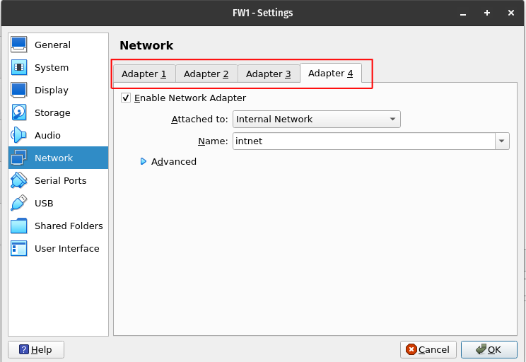
Firstly, if you’ve been following along with this project, you may have noticed that the VirtualBox GUI only gives you options to add 4 network adapters to a virtual machine (VM):
For this project however, I have the WAN connection, DMZ, and LAN (Empty) already setup on three of the ports. I am going to need five additional ports to setup segments for the rest of my departments. Luckily, VirtualBox actually supports up to 8 NICs (Network Interface Cards) per VM, they just have to be setup through the command line.
Before moving to command line though, I’m going to setup Adapter 2, 3 and 4 for the pfSense using the GUI. I’m only going to show what I did for Adapter 4 here so that you understand what is happening. First, I’ll open FW1 settings and navigate to Network. Above, you can see that the adapter is set to an Internal Network with the name ‘intnet’. This is the current setup for adapters 2,3, and 4. However, using the same ‘intnet’ internal network for all the adapters is going to create problems going forward. Remember, I’m connecting each machine directly to the pfSense so imagine that I need a CAT5e cable for each machine to connect to each port of the firewall. Each internal network is going to act as a CAT5e cable, so they need unique names so that the pfSense knows which machine is connected to which port, and the machines know which port of the pfSense they are connected to.
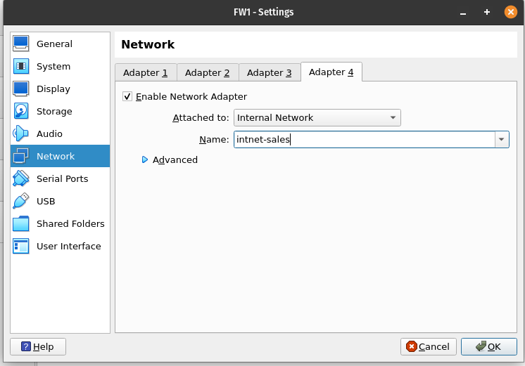
I’ll open adapter 4 and change the Internal Network to ‘intnet-sales’. This identifies that this port is going to be used for the Sales machine:
Next, I’ll open the settings for the Sales VM and change its internal network to the same name:
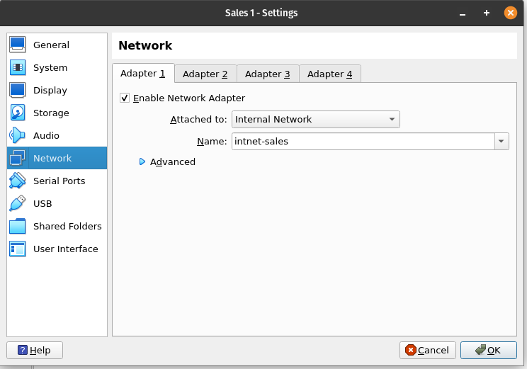
Now, every time the firewall and the Sales machine need to communicate, they will do so over the ‘intnet-sales’ network. I’ll do the same for Adapter 2 and 3 (Adapter 1 is the NAT Internet connection). Adapter 3 is for the DMZ so I’ll leave it on ‘intnet’ and I’m keeping Adapter 2 as an extra adapter in case I want to add a new machine at a later stage. For now, I’ll rename Adapter 2’s network to ‘intnet-lan’.
To set up the rest of the adapters, on the host PC (The PC running VirtualBox), open up terminal (I run Linux as my Native OS). First of all, I want to check out the current setup of my existing NICs on the FW1 machine so that I can set the new ones up in the same manner. To do this, I’ll run the VBoxManage tool (Remember to change user to the root user, or use sudo in front of these commands):
VBoxManage showvminfo “FW1” –details
The problem with this command is that it drops every detail of information about the VM, 99% of which I don’t need to see. So I’ll modify the command to grep only the lines that I’m interested in:
VBoxManage showvminfo “FW1” –details | grep NIC
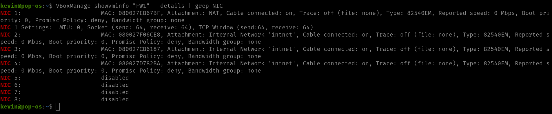
As seen above, there are actually 8 adapters I can use.
So now I need to enable NIC 5 through 8 and make sure that they attach themselves to the internal network. I’ll use this command:
VBoxManage modifyvm FW1 –nic5 intnet –intnet5 intnet-hr –macaddress5 auto
This command will need to be run 4 times while changing the 5’s to 6,7,8 and giving each network a unique name. Once done, run the showvmdetails command as before to check if everything is setup correctly:
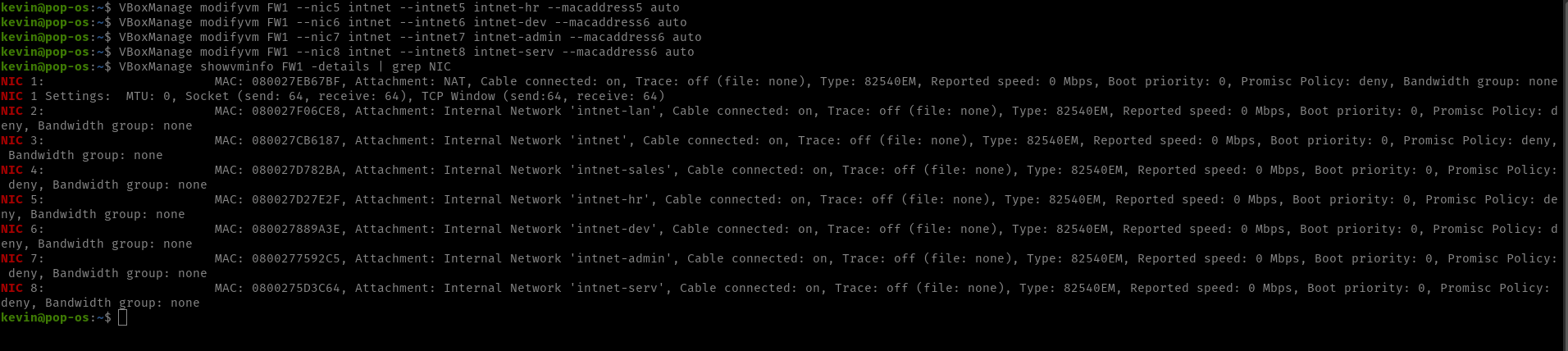
As seen above, I now have unique networks setup for each adapter. All that remains is to open each VM and change their Network Adapters to the correct network.
Once done, start the pfSense and navigate to Interfaces > Assignments:
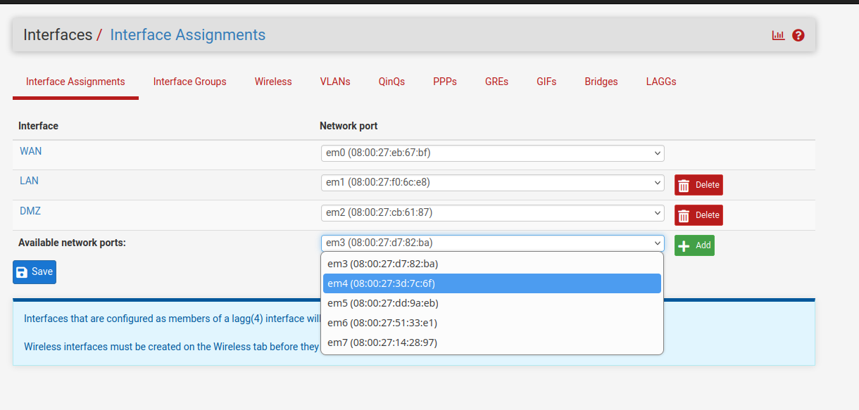
I now have adapters em3 to em7 to work with. Each one of them will be used for a different segment. Add them all by selecting each one and clicking the add button:
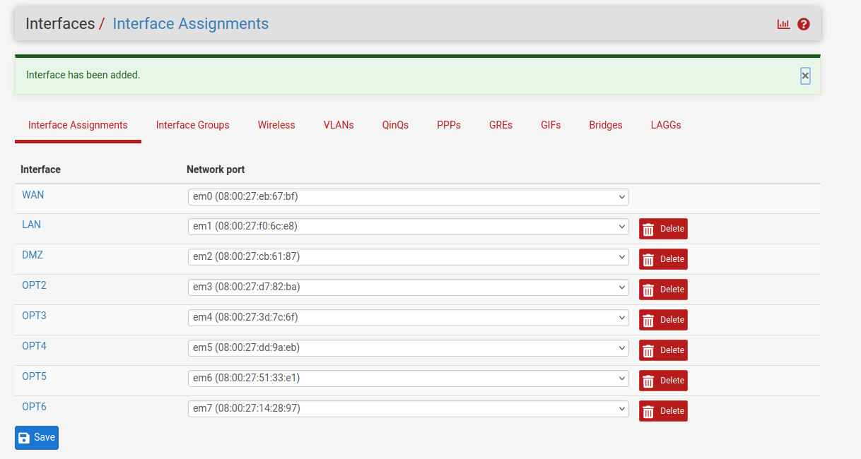
The first segment I’m going to set up is the Sales department with the Windows 11 client. Click on OPT2 to open the configuration:
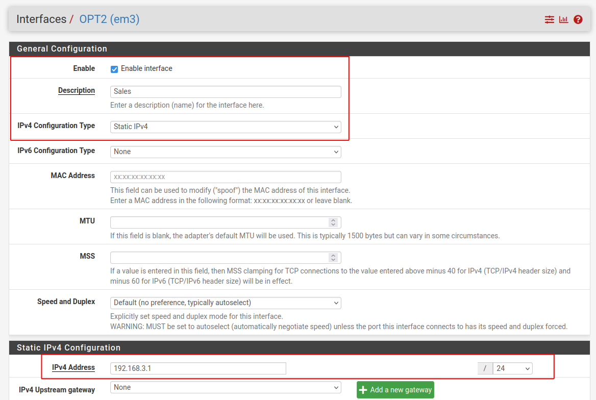
Make sure to check ‘Enable Interface’. Write the name of the segment, in this case ‘Sales’, in the description box. For IPv4 Configuration Type select ‘Static IPv4’ and give the segment an IP range to use. In this case I’m using 192.168.3.1/24. This gives the department the ability to grow to 253 clients or devices, which should be more than enough for this business.
Next, go to Services > DHCP Server and select Sales: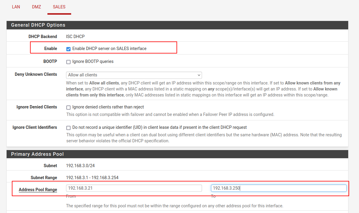
Enable DHCP on the Sales Interface and then enter the address pool range. I am starting my range at 21 and ending it at 250 so that I have some room for static addresses. Click Save and then apply the changes.
Now, I’ll boot up the Sales VM and run ipconfig to check if my changes have taken effect:

Perfect. Notice that it has assigned an IP from within the DHCP address pool. The only issue now is that I don’t have internet access because the firewall is blocking me:

So now I have to set up a quick rule to allow this machine to access the internet. Open Firewall > Rules and select Sales:
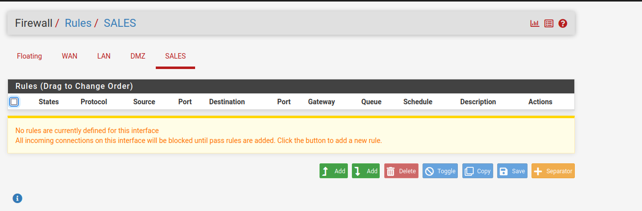
Click the Add button with the upwards arrow:
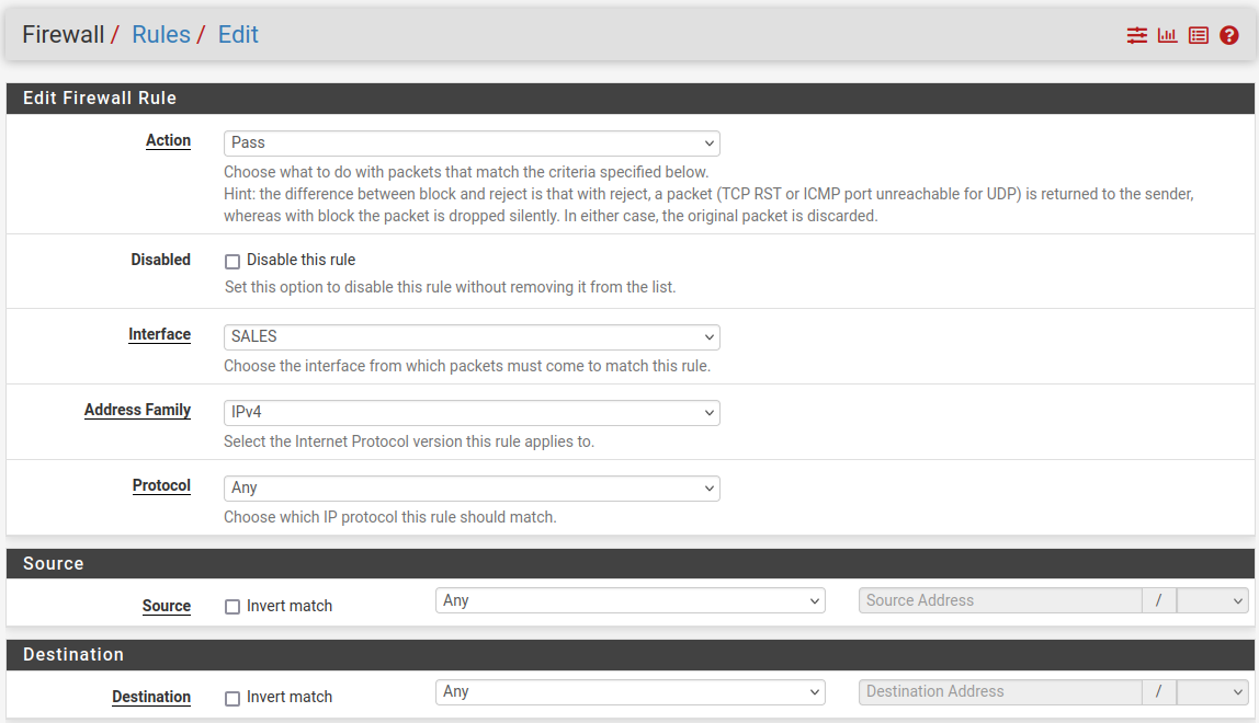
Under Action select ‘Pass’, under Interface select SALES, under Address Family select ‘IPv4’ and under Protocol select ‘Any’. This means that any traffic will be able to flow to and from this network segment. This is not safe! But I will be setting up proper rules in the next part of this project. For now, open the Sales VM and check if it can reach the internet:
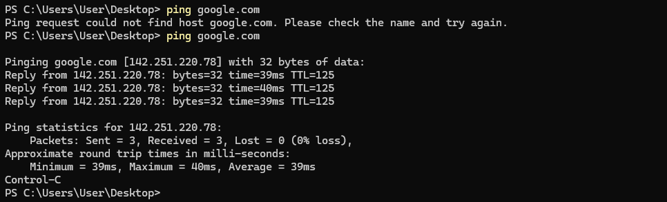
Success! Now I’ll just repeat these steps for the rest of the clients on the network. Once finished, my pfSense console menu looks like this:


